
Cómo elegir microherramientas internas para mandrinado, ranurado y roscado
Choosing micro internal tools is rarely a diameter-only decision. A bar may enter the bore and still be too long, too flexible or unable to clear the chips.
This guide follows the same order we use when reviewing a small-bore application: define the internal feature, check access and rigidity, then look at material, coolant and cutting conditions. It also gives buyers and tooling suppliers a practical way to compare an existing model and approve samples before a production order.
Micro Internal Tools: Quick Selection Table
Use the operation and internal feature to identify the tool family. Final selection still depends on the exact dimensional chart and application data for the model.
| Internal operation | Typical tool family | Main dimensions to confirm |
|---|---|---|
| Bore enlargement or finishing | Micro boring or profiling bar | Starting and finished bore, depth, tolerance and surface finish |
| Radial internal groove | Micro internal grooving bar | Minimum bore, groove width, depth, position and bottom radius |
| Thread relief or undercut | Thread-relief grooving bar | Relief width, diameter, runout position and adjacent thread |
| Internal face groove | Micro face-grooving bar | Groove diameter range, axial depth, tool hand and entry direction |
| Back turning or reverse profile | Back-turning or profiling bar | Entry bore, profile envelope, feed direction and withdrawal clearance |
| Internal thread | Micro internal threading bar | Standard, pitch/TPI, diameter, length, hand and thread relief |
Swipe horizontally to view the full table.
Micro Internal Tool Series at a Glance
After identifying the machining operation, use the chart below to narrow down the suitable micro internal tool series. Different tool geometries are designed for boring, radial grooving, face grooving, profiling and internal threading, with different limits for minimum bore diameter, groove width, nose radius and machining depth.
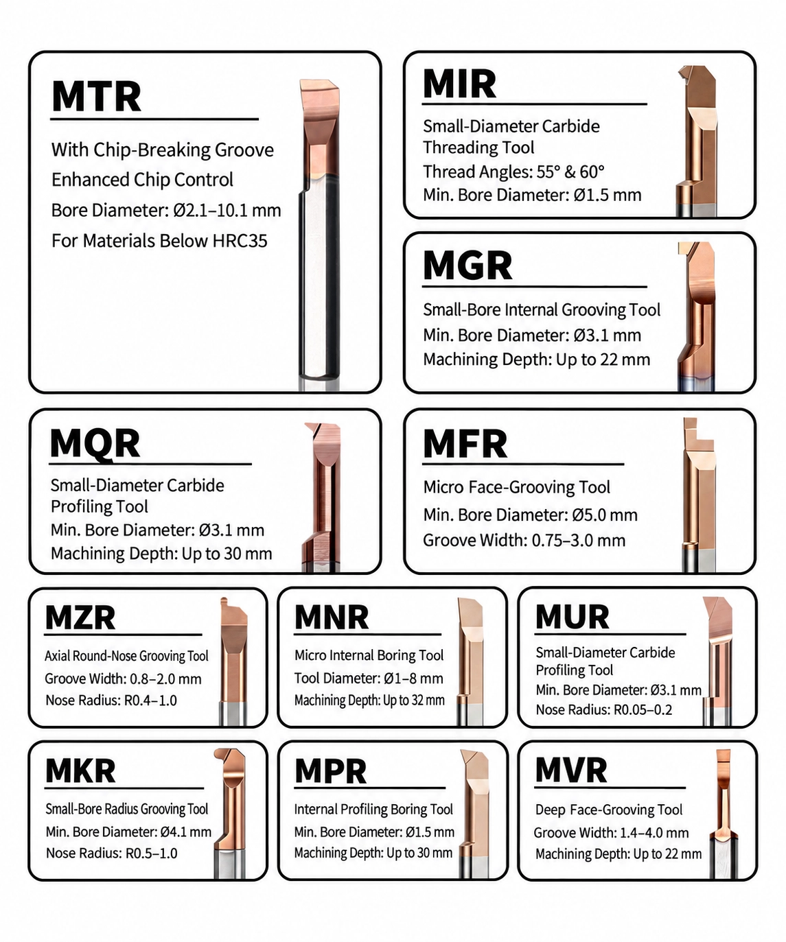
This chart is intended as a quick series reference rather than a final model-selection table. Once the likely tool family has been identified, confirm the exact DMIN, working depth, groove dimensions, nose radius, thread form and tool clearance against the dimensional data for the selected model.
The complete selection process can be organized into seven practical checks, as summarized below.
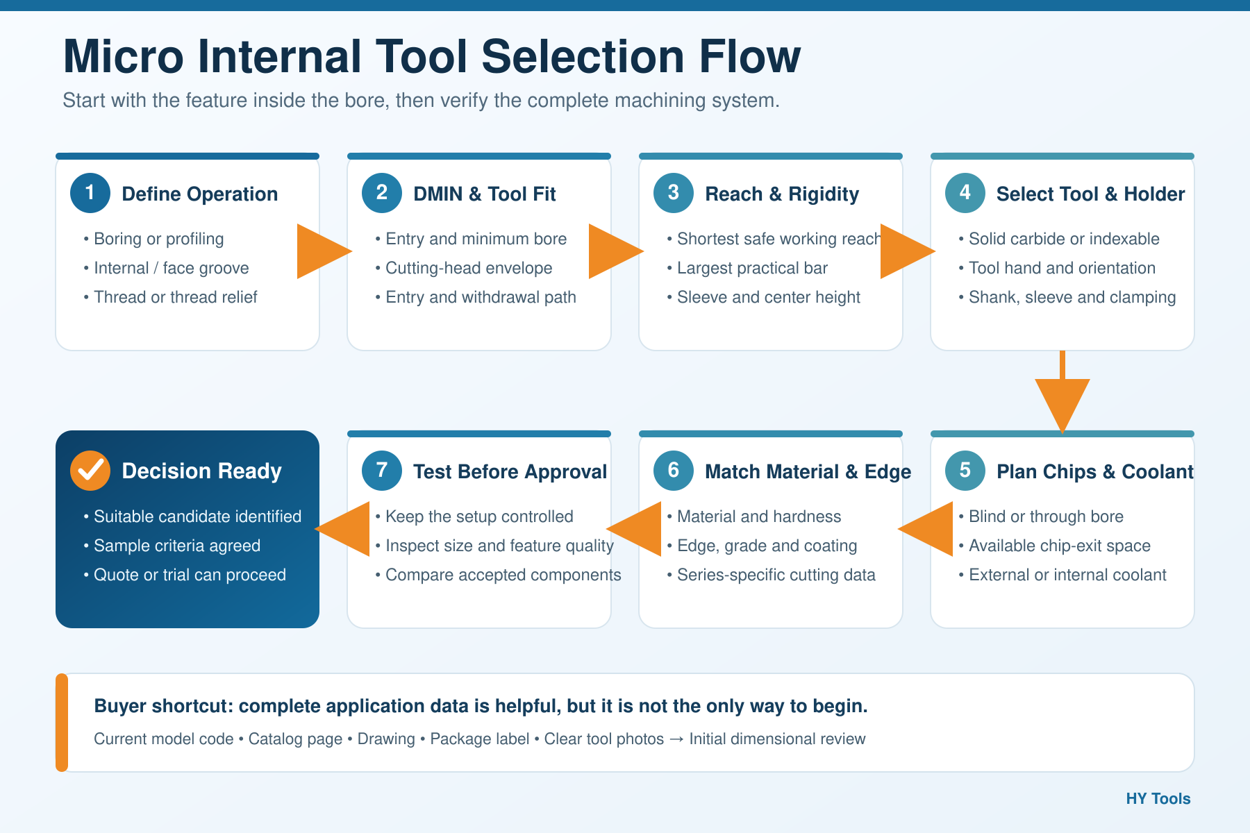
1. Define the Exact Internal Operation
Similar shank diameters do not make tools interchangeable; the cutting edge, neck relief and feed direction are designed around a particular feature.
Micro boring bars enlarge, finish or profile an existing bore. Micro internal grooving tools reach a defined axial position and cut radially or along a specified profile. Micro threading bars generate a thread through synchronized spindle rotation and feed.
A radial-grooving tool may not have the clearance or cutting direction needed for face grooving, thread relief or back turning.
2. Start with the Information You Already Have
Some enquiries arrive with a complete drawing; others start with an old model code, catalog page or package label. We can work from either.
- New application: provide the operation, bore dimensions, internal feature, reach, material, machine and quality target.
- Existing-model replacement: provide the current brand and model, dimensional chart, catalog page or drawing.
- Limited information: provide clear photos of the cutting head, shank marking, package label and the quantities required by model.
For an end-customer requirement, HY Tools can compare the available geometry first and list the missing checks. We will not call two tools equivalent from appearance alone: DMIN, reach, clearance, cutting direction, edge preparation, grade and coating may still differ.
3. Confirm the Minimum Bore Diameter for Micro Internal Tools
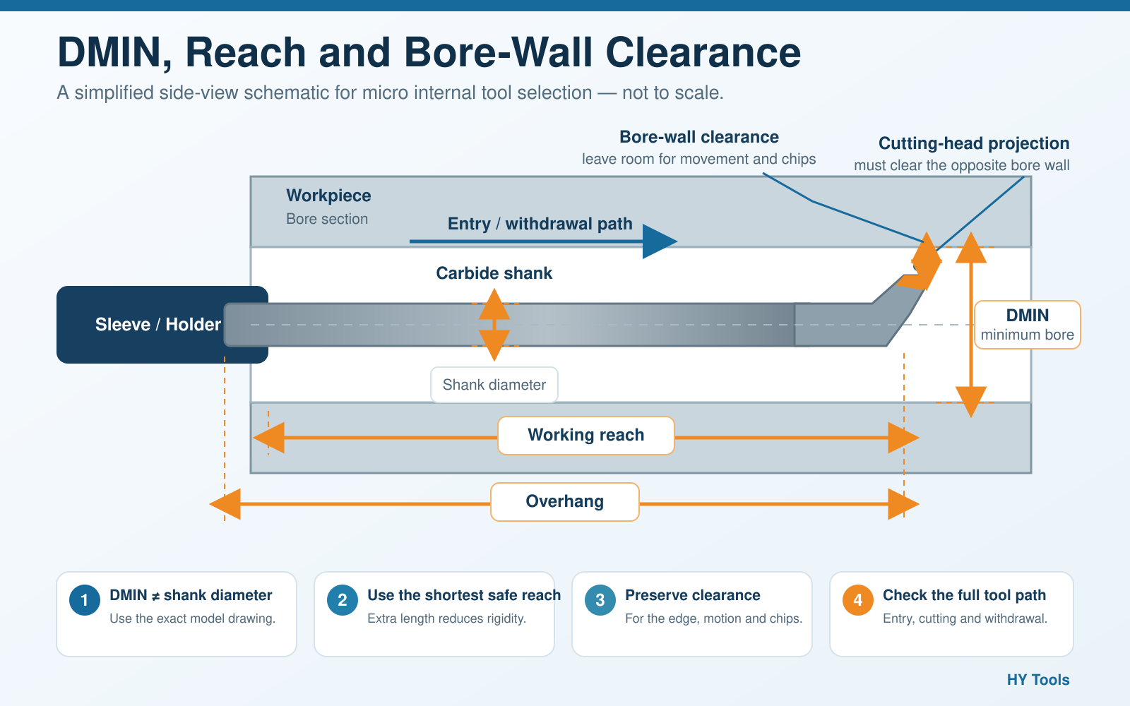
One of the most important specifications for micro internal tools is the minimum machinable bore, often shown as DMIN. DMIN is not the same as shank diameter.
For example, a 4 mm carbide shank does not automatically fit a 4 mm bore. The cutting edge may project beyond the shank, the neck needs relief behind the edge, and the complete cutting profile must clear the opposite wall during entry, cutting and withdrawal.
Work through these dimensions:
- Bore entrance diameter and the smallest diameter along the tool path
- Diameter at the actual cutting position
- Maximum cutting-head envelope
- Clearance behind the cutting edge
- Internal shoulders, tapers or steps
- Entry and retraction movement
This is where a dimensional chart matters more than a product photo. The broader micro internal tooling range identifies the family, but the exact model chart must show that the tool really fits.
The relationship between shank diameter, DMIN, working reach and bore-wall clearance is illustrated below.
4. Control Working Reach, Bar Diameter and Rigidity
Use the shortest reach that safely reaches the feature. Extra length increases overhang and may show up as bore taper, an inconsistent groove position, chatter or early edge failure.
“Use the largest bar” also needs context:
- A larger practical bar generally improves stiffness.
- A smaller bar leaves more room for the cutting edge, movement and chips.
The correct choice is the largest practical bar that still leaves chip clearance, consistent with Sandvik Coromant’s internal turning setup guidance.
5. Choose Micro Internal Tool Construction and Holder
Solid-carbide bars keep the cutting head compact and are often the practical starting point for restricted bores. Tungaloy’s TinyMiniTurn system is one example. Indexable tools become practical when the bore can accommodate the insert and clamping structure, offering replaceable edges and more grade options.
The holder is part of the cutting system. Check:
- Correct sleeve and shank fit
- Sufficient clamping length
- Tool center height and orientation
- Holder, turret and component interference
- Coolant-port alignment, when applicable
Do not compensate for an inaccurate or damaged sleeve by changing coating or cutting speed.
If a standard micro internal tool cannot provide the required bore access, reach, clearance or cutting profile, a
custom cutting tool
can be reviewed from your drawing, existing tool or application requirements.
6. Plan Chip Evacuation and Coolant Delivery
The chips still need a way out of a small bore. Without one, expect recutting, scratches, packing around the bar and edge damage. Blind holes are more demanding because chips cannot continue through the component; Sandvik also identifies overhang and chip evacuation as key challenges in internal grooving.
External coolant can work when it reaches the edge and chips have a clear exit. Precision or internal coolant can deliver fluid closer to the cutting zone in deeper or more restricted applications. Through-coolant is not universally required; use the delivery method and pressure approved for the actual system.
Have a Model List but Not the Complete Machining Data?
Send the current model code, catalog page, drawing, label or clear tool photos. We can compare the available dimensions and identify what your end customer still needs to confirm before sample selection.
7. Match Micro Internal Tools to the Workpiece
Coating selection comes later than many buyers expect. First make sure the tool can enter, reach, cut and retract with enough rigidity. Then match the edge geometry, carbide grade and coating to the workpiece and cutting condition.
| Workpiece group | Main selection priorities |
|---|---|
| Carbon and alloy steel | Stable edge, wear resistance and predictable chip control |
| Acero inoxidable | Sharp cutting action, low cutting force and reliable chip evacuation |
| Hierro fundido | Wear resistance and sufficient edge support |
| Aluminium and non-ferrous alloys | Sharp edge, low adhesion and adequate chip space |
| Hardened material | Grade and geometry approved for the actual hardness and interruption |
Swipe horizontally to view the full table.
Do not identify a coating from colour alone. Similar-looking coatings may use different compositions, edge preparations and application ranges.
8. Set Up Boring, Grooving and Threading Correctly
| Operation | Dimensions and setup | Main process risk |
|---|---|---|
| Micro boring | Starting/finished bore, stock, depth, tolerance, finish, center height | Deflection, bore taper, chatter and poor chip evacuation |
| Internal grooving | Width, depth, axial position, radius, approach and radial engagement | Excess cutting force, wrong groove position and trapped chips |
| Internal threading | Profile, pitch, alignment, center height, infeed, passes and runout | Wrong profile, chip packing, vibration and insufficient bottom clearance |
Swipe horizontally to view the full table.
For internal threading, Sandvik’s thread-turning guidance also emphasizes pass selection, chip control and tool alignment.
After the tool geometry and setup have been confirmed, use the HY Tools speeds and feeds resources as a starting reference for cutting parameters. Final values should still be adjusted for the exact tool model, workpiece material, overhang, coolant and machine rigidity.
For internal threading, Sandvik’s thread-turning guidance also emphasizes pass selection, chip control and tool alignment.
9. Identify Internal Threads Beyond the Included Angle
A 60° included angle does not by itself identify a Metric, Unified or tapered pipe thread. A 55° tool is not automatically correct for every 55° thread either.
| Specification group | What to provide | Por qué es importante |
|---|---|---|
| Thread identity | Standard, designation, included angle and pitch/TPI | Angle alone cannot identify a compatible profile |
| Thread form | Parallel/tapered and full-/partial-profile requirement | Controls cutting profile and diameter coverage |
| Bore geometry | Internal diameter, pre-bore, thread length, runout and bottom clearance | Controls access, reach and safe withdrawal |
| Direction | Thread hand, tool configuration and programmed feed direction | These are separate selection items |
| Acceptance | Class, tolerance or gauge standard | Defines how the finished thread will be approved |
Swipe horizontally to view the full table.
10. Evaluate Micro Internal Tools Before Bulk Purchase
A sample comparison is only useful when the setup stays the same. Use the same material, component, bore, tool reach, sleeve, coolant and machine. Begin with the data recommended for the exact series and change one variable at a time.
| Operation | Approval evidence |
|---|---|
| Boring | Bore size, taper/cylindricity, surface finish, stability and wear pattern |
| Grooving | Groove width, depth, axial position, bottom profile, burr and chip evacuation |
| Threading | Gauge result, thread profile, effective length, runout, chip control and edge condition |
| All operations | Breakage rate, repeatability, tool life and cost per accepted component |
Swipe horizontally to view the full table.
Tool life alone is not a sufficient approval criterion if bore size, groove position or thread quality has already moved outside the specification.
For downloadable machining references and technical PDFs, visit our
Catálogos y descargas
page, including the Micro Internal Tooling speeds and feeds guide.
11. Practical Existing-Model Replacement Example
Suppose a tooling supplier receives an end customer’s list containing a coated micro grooving bar with a 4 mm shank, but no component drawing. The replacement should move through four checks:
- Identify: send the complete model code, catalog image and package photo.
- Compare: check shank size, DMIN, cutting width, groove-depth capacity, effective length, tool hand and coating designation.
- Fill the gaps: ask for the actual entry bore, groove position, material, coolant and quantity before confirming a trial.
- Approve: test both tools under the same setup and record groove size, position, surface condition, chip evacuation and stable part count.
This avoids calling a visually similar 4 mm-shank bar an equivalent before its geometry and performance have been demonstrated.
12. Prepare a Clear RFQ for Micro Internal Tools
| RFQ situation | Enviar primero | Confirm before sample approval |
|---|---|---|
| New application | Drawing, operation, bore/feature dimensions, material and quantity | Reach, tolerance, machine, sleeve, coolant and cutting conditions |
| Existing-model replacement | Brand, complete code, catalog page, label and required quantity | Dimensional equivalence, application limits and test criteria |
| Limited information | Clear head, shank and package photos plus known dimensions | Missing geometry and end-customer application data |
| Custom requirement | Dimensioned drawing, material, tolerance and expected volume | Manufacturability, inspection method, trial quantity and lead time |
Swipe horizontally to view the full table.
A model number, drawing, catalog page or clear photo is enough for us to begin; complete application data is still needed before final approval.
13. Avoid Common Micro Internal Tool Selection Mistakes
- Selecting from shank diameter instead of the exact DMIN and cutting-head envelope
- Ordering unnecessary working length and losing rigidity
- Using the largest physical bar without preserving chip clearance
- Treating radial, face and thread-relief grooving tools as interchangeable
- Ordering a threading tool from angle alone
- Confusing thread hand, tool hand and feed direction
- Copying cutting data from another diameter or tool series
- Ignoring center height, sleeve condition, coolant access and withdrawal clearance
- Approving a replacement from appearance or price without controlled testing
Preguntas frecuentes
What is the minimum bore diameter for a micro internal tool?
There is no universal minimum. Use the DMIN or equivalent minimum-machining-diameter value for the exact model and check the full entry, cutting and retraction path.
Is shank diameter the same as minimum bore diameter?
No. Cutting-edge projection, neck relief, tool orientation and bore-wall clearance can make the required minimum bore larger or smaller than a simple comparison with shank diameter suggests.
Should I use the largest boring bar that fits?
Use the largest practical bar that reaches the feature while preserving enough room for the cutting edge, movement and chip evacuation.
Can an existing model number be used to request an alternative?
Yes. Send the brand, complete model code and any catalog or package information. The available dimensions can be compared first, but application details and sample testing are still required before claiming equivalent performance.
What information is essential for a micro threading bar?
The essential information is the thread standard, pitch or TPI, diameter, thread length, hand, parallel or tapered form, runout, pre-bore, tool orientation, workpiece and required tolerance or gauge.
Request a Standard or Custom Tool Recommendation
Send the application data, current model list, drawing or clear tool photos. HY Tools can review a standard replacement or a drawing-based micro boring, grooving or threading configuration—and tell you what still needs to be checked before sample testing.