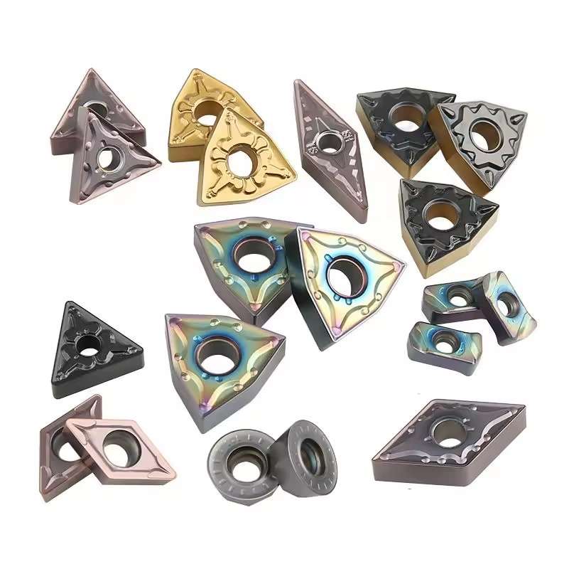
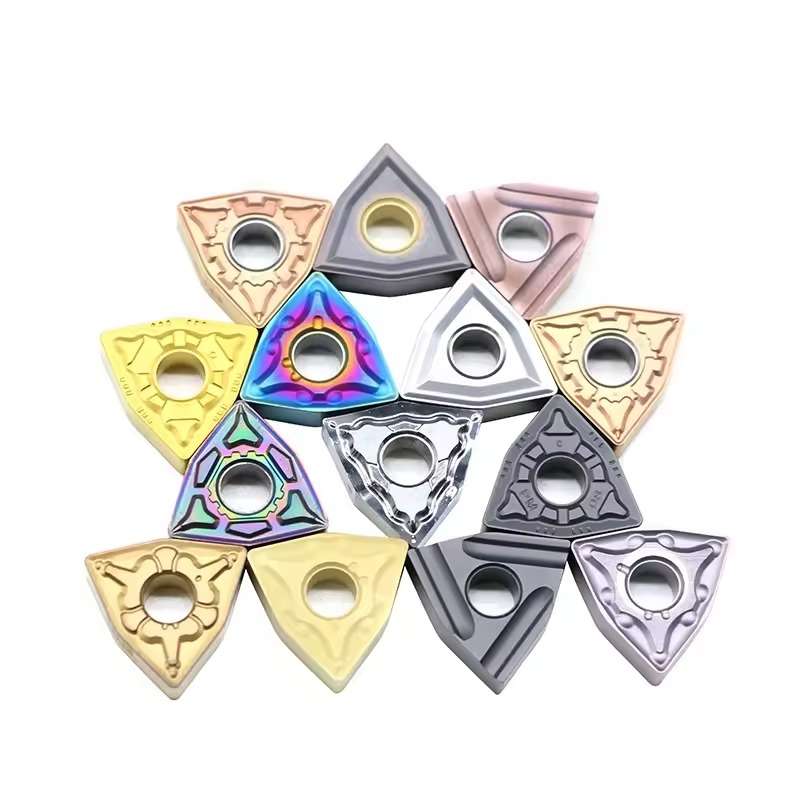

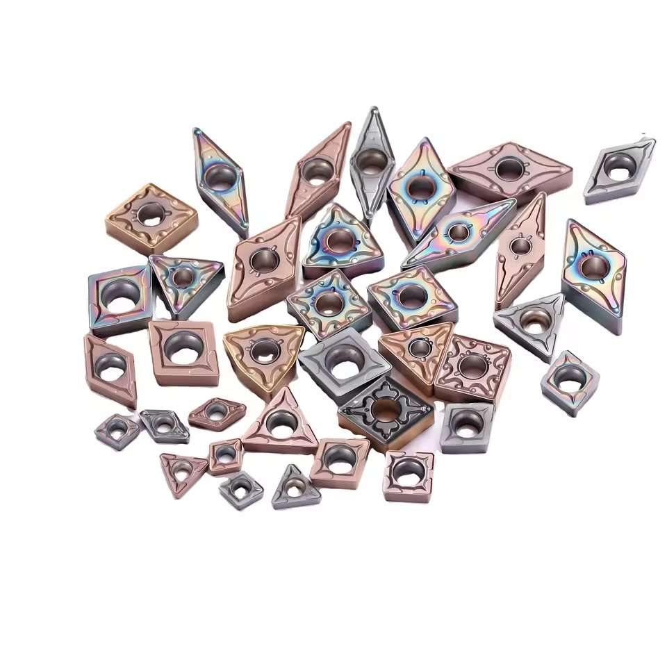




Carbide Turning and Milling Inserts for CNC Machining
This carbide insert range covers common CNC turning and milling applications for steel, stainless steel, cast iron, aluminum and other grade-dependent materials. Multiple insert shapes, sizes, coatings and chipbreakers allow wholesalers to build a broader cutting-tool assortment, support model replacement and combine selected products into mixed-model distributor orders.
جودة متسقة
Consistent geometry across repeat orders.
الطلبات المرنة
Small batches and mixed sizes available.
OEM Support
Custom marking, labels and packaging.
قياسي ومخصص
Standard sizes and custom configurations.
◆نظرة عامة على المنتج
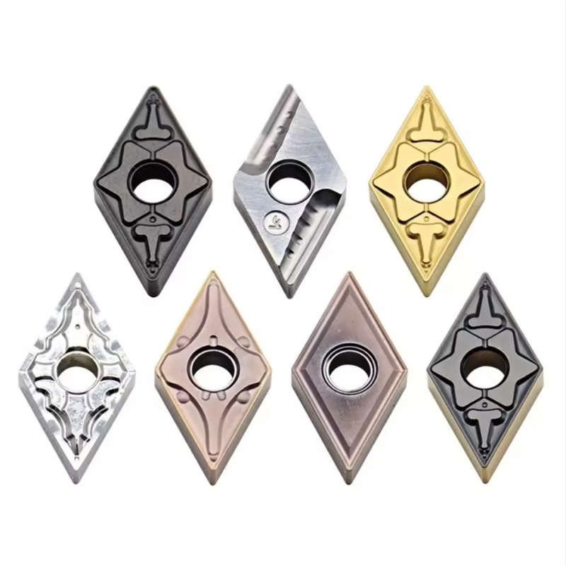
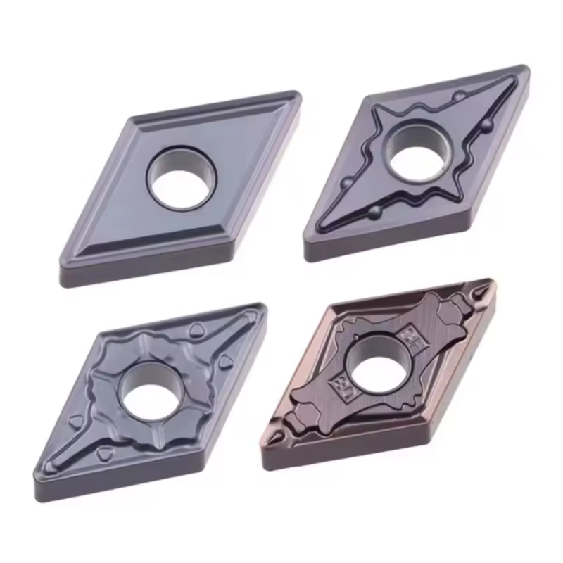
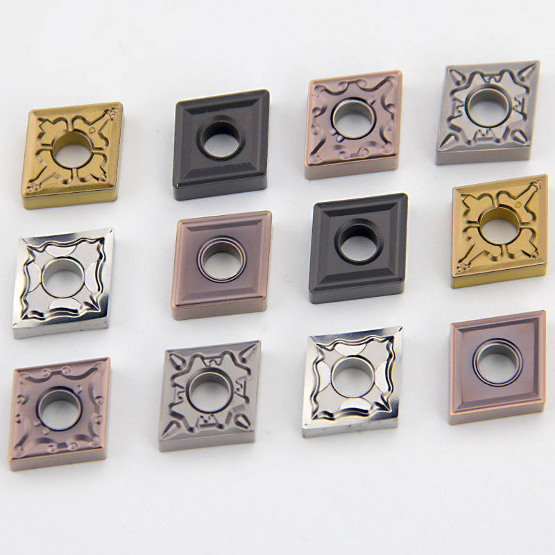
إن Carbide Turning and Milling Inserts for CNC Machining range covers indexable cutting inserts for external turning, facing, profiling, roughing, semi-finishing, finishing, shoulder milling, face milling, and other production operations. Common turning families include CNMG, DNMG, SNMG, TNMG, VNMG, and WNMG, while APMT and other dedicated geometries are used with compatible indexable milling cutters.
The insert shape alone does not define the application. Size, clearance angle, tolerance, corner radius, chipbreaker, carbide grade, coating, and holder or cutter-pocket compatibility must be checked together. For shoulder and face milling, compare the APMT1604 / APMT1135 milling insert series.
إدخالات الطحن
PVD / CVD Grades
تصنيع المعدات الأصلية وتصنيع المعدات الأصلية

◆Turning Inserts vs. Milling Inserts
Both products use indexable carbide cutting edges, but their motion, clamping systems, geometry, and loading are different. They must be matched to the correct holder or cutter body.
إدخالات الخراطة الكربيدية
The insert is clamped in a stationary toolholder while the workpiece rotates. Shape and included angle determine edge strength, access, profiling capability, and the number of usable cutting corners.
- ◆External turning and facing
- ◆Roughing, semi-finishing, and finishing
- ◆Profiling, chamfering, and contour access
Carbide Milling Inserts
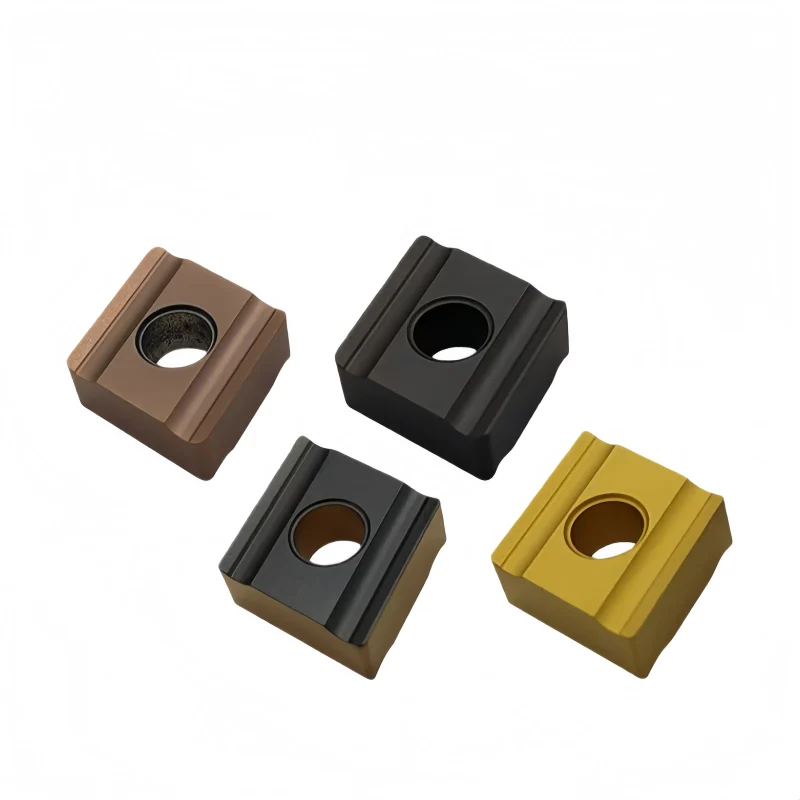
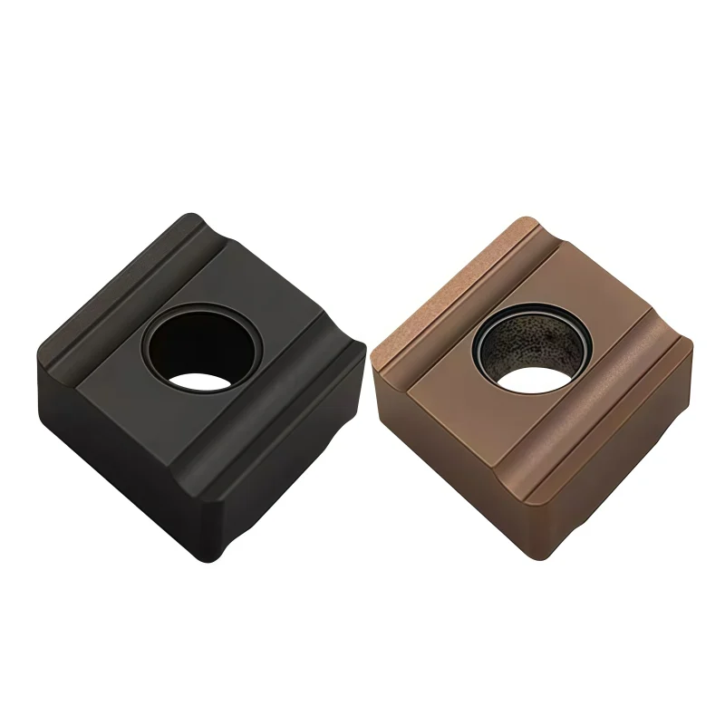
Multiple inserts rotate with the cutter body and repeatedly enter and leave the cut. The insert must withstand cyclic impact while maintaining pocket seating, chip evacuation, and edge-height consistency.
- ◆Face and shoulder milling
- ◆Slotting, side milling, and profiling
- ◆High-feed and specialized indexable operations
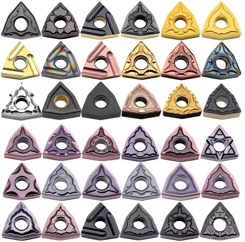

◆Common Insert Families & Their Roles
The descriptions below are general geometry guidelines. The complete ISO code and manufacturer suffix determine the actual dimensions, corner radius, tolerance, chipbreaker, and grade.
| Family | General Shape | Main Strength | Typical Use |
|---|---|---|---|
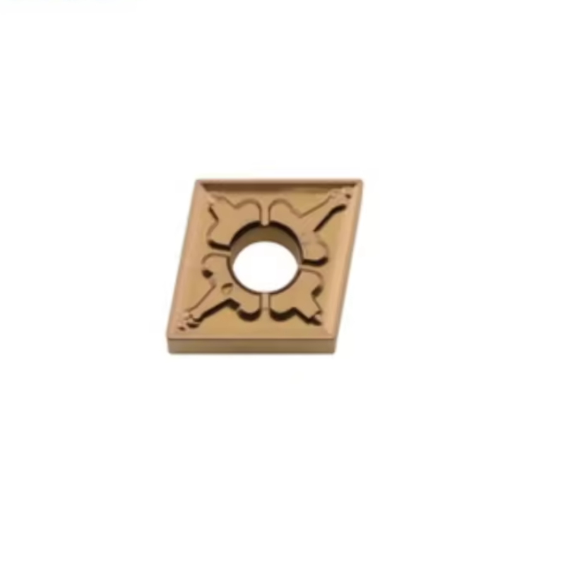
| CNMG | Strong diamond turning insert | Balance of strength and accessibility | General external turning, facing, roughing, and semi-finishing |
| DNMG | Narrow diamond turning insert | Improved profile access | Profiling, contour turning, semi-finishing, and finishing |
| SNMG | Square negative turning insert | Strong corners and economical indexing | Stable roughing and heavy general turning |
| TNMG | Triangular negative turning insert | Multiple cutting corners and versatility | General turning, facing, and medium profiling |
| VNMG | Very narrow diamond turning insert | Excellent access to fine contours | Precision profiling, finishing, and restricted features |
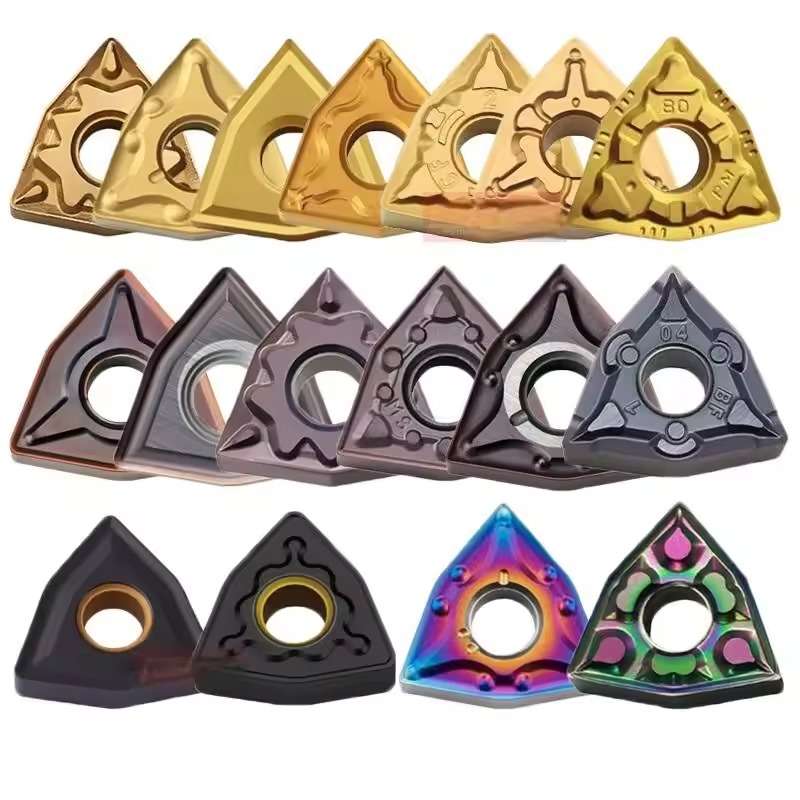
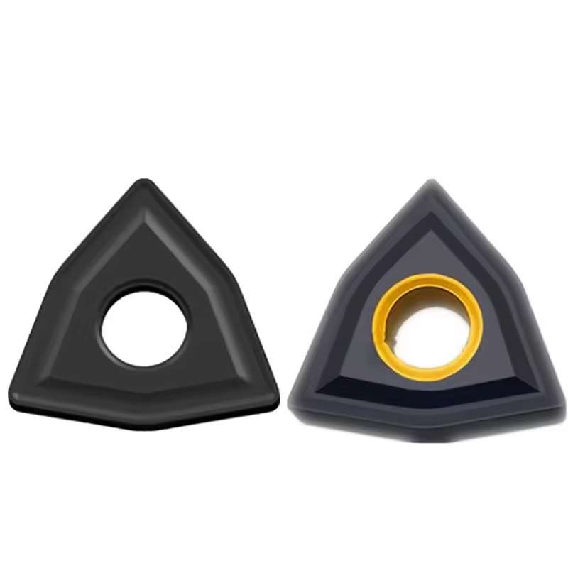
| WNMG | Trigon negative turning insert | Strong geometry with multiple usable edges | General turning, facing, roughing, and production work |
| APMT | Positive milling insert | Lower cutting pressure and shoulder access | Shoulder, face, slot, side, and profile milling with a compatible cutter |
For a deeper explanation of insert shapes, relief angles, workpiece groups, and chipbreakers, read the carbide insert types guide.
◆Match the Grade to the Workpiece
◆Insert Geometry & Coating Details


◆Coating, Chipbreaker & Edge Preparation
PVD-Coated Grades
Often selected when edge sharpness, coating toughness, and lower cutting pressure are important. Suitability depends on the substrate and application.
CVD-Coated Grades
Commonly chosen for strong wear and heat resistance in stable steel or cast-iron machining. Edge requirements must still be confirmed.
Chipbreaker Geometry
Controls chip formation within a defined feed and depth range. A roughing chipbreaker should not be treated as a finishing geometry, or vice versa.
For high-productivity milling with shallow axial engagement, compare the
LNMU / ENMU / BLMP double-sided high-feed inserts.
◆Product Range Reference
| Product Type | Indexable carbide turning and milling inserts |
| Turning Families | CNMG / DNMG / SNMG / TNMG / VNMG / WNMG and other models |
| Milling Families | APMT and other indexable milling geometries according to cutter body |
| Machining Level | Roughing / semi-finishing / finishing, chipbreaker dependent |
| Workpiece Materials | Steel / stainless steel / alloy steel / mold steel / cast iron, grade dependent |
| خيارات الطلاء | PVD / CVD / uncoated according to model and application |
| Compatibility | Matched turning toolholder or indexable milling cutter pocket |
| Reference Packaging | 10 pieces per box; confirm by model |
| الخدمة | Standard supply / grade matching / OEM & ODM / custom packaging |
◆Compatibility Checklist
◆Common Insert Wear Patterns
| Wear Pattern | Possible Cause | Checks and Adjustments |
|---|---|---|
| Rapid Flank Wear | Speed too high or grade lacks wear resistance | Review cutting speed, coating, carbide grade, and coolant strategy |
| Edge Chipping | Impact, vibration, weak edge, or unstable clamping | Check holder pocket, screws, overhang, feed, interruption, and edge hone |
| Built-Up Edge | Rubbing, adhesion, low speed, or unsuitable grade | Maintain chip load and verify sharpness, coating, coolant, and material group |
| Crater Wear | Excessive heat and chip flow across the rake face | Review speed, coating, chipbreaker, feed, and heat evacuation |
| Poor Surface Finish | Worn edge, runout, incorrect nose radius, or chatter | Inspect setup rigidity, tool height, pocket condition, edge indexing, and feed |
◆Related Insert Solutions
APMT1604 / APMT1135 R0.8
Positive indexable inserts for shoulder, face, slot, side, and profile milling.
LNMU / ENMU / BLMP Inserts
Double-sided inserts for high-feed roughing and semi-finishing with shallow axial engagement.
16IR / 16ER Thread Inserts
Internal and external indexable threading inserts for defined ISO thread profiles and pitches.
APMT1135 Coated Carbide Inserts
A focused APMT1135 option for compatible indexable milling cutters and selected CNC milling operations.
◆Specifications & Product Range
This page covers multiple indexable turning and milling insert families. The Overview identifies product families and application options but does not provide a verified size-by-size catalog for the whole range. Specify the complete insert designation and holder or cutter-body model to obtain the correct dimensional drawing, grade and availability for a particular item.
| Product Group | Families in Overview | Operation | Required Fit Check |
|---|---|---|---|
| Turning inserts | CNMG / DNMG / SNMG / TNMG / VNMG / WNMG | External turning, facing, roughing, semi-finishing, finishing or profiling as geometry permits | Holder pocket, insert code, seat, clamp, orientation and corner clearance |
| Milling inserts | APMT and other cutter-specific geometries | Shoulder, face, side or profile milling according to cutter design | Cutter-body model, pocket, screw, insert size, handedness and usable corner |
◆Specification Checklist by Model
| المعلمة | What to Confirm for the Exact Insert |
|---|---|
| Full ordering code | Family, ISO body code, numeric size, corner radius, manufacturer chipbreaker suffix and grade code |
| الأبعاد | Inscribed circle or equivalent size, thickness, cutting-edge length, fixing-hole details and corner radius from the model drawing |
| Cutting geometry | Finishing, medium or roughing chipbreaker; rake, edge preparation and applicable feed/depth range |
| Grade and coating | Carbide substrate grade; PVD, CVD or uncoated finish if offered for the model; approved workpiece group |
| Tool compatibility | Turning holder or milling cutter model, pocket seat, clamp/screw and cutting direction |
| Pack and supply | The Overview gives 10 pieces per box as a reference only; confirm pack quantity, MOQ, mixed-model availability and lead time by code |
◆How to Select a Compatible Insert
For the turning-insert decision process, see the CNC Insert Selection Guide. For milling dimensions, use the APMT1135 / APMT1604 series as a series-specific reference.
◆Starting Cutting Data
A single speed, feed or depth of cut is not valid across the turning and milling families on this page. Request starting parameters for the complete insert code, carbide grade, chipbreaker, workpiece material and holder or cutter body. Turning feed is commonly stated per revolution; milling feed must account for tooth count and actual engagement.
◆Series-Specific Size References
For exact dimensions and orderable variants, consult the relevant series page or send the original insert code and drawing. The APMT milling insert series covers a focused milling family. This page serves as a product-range and matching reference rather than a combined dimensional catalog.
◆Carbide Insert Customization & OEM
Specify the insert around the machining operation, workpiece and holder. We can review standard replacements, application-specific geometry and private-label requirements using your insert designation, drawing or sample. Available grades, coatings, dimensions and order quantities are confirmed for each requested series.
Geometry & Chip Control
Review chipbreaker, rake, cutting-edge preparation, nose radius and corner design for the operation and workpiece. Confirm holder compatibility before approving a modified geometry.
Substrate & Coating
Select an available carbide grade and coating for the workpiece material, cutting conditions and desired balance of wear resistance and edge toughness.
Dimensions & OEM
Review insert size, thickness, locating and clamping features, tolerances, laser marking and private-label packaging against the approved specification.
◆Customization Options
Use the fields below when sending an inquiry. The exact options depend on the insert family and are confirmed in the quotation or approved drawing.
| المواصفات | Details to Confirm |
|---|---|
| Insert Type | Turning, milling, threading, grooving or drilling insert; send the designation or drawing. |
| Size & Fit | Shape, size, thickness, inscribed circle or edge length, hole or clamping form, and holder model. |
| هندسة القطع | Chipbreaker, nose or corner radius, edge preparation, cutting direction and application-specific profile. |
| Grade & Coating | Workpiece group and grade, carbide substrate, coating system and wet or dry cutting conditions. |
| Tolerance & Inspection | Critical dimensions, profile requirements, inspection method and any required report. |
| OEM Presentation | Insert or box marking, label content, packaging format and quantity per pack. |
◆How to Request a Custom Insert

Send your insert requirements through our contact form or review our OEM and private-label service.
◆Carbide Insert Quality Control

Insert quality depends on the approved grade, geometry, coating and dimensional specification. We review the requirements at order confirmation and align the inspection scope with the insert series and any customer drawing. Share critical dimensions or documentation needs before production so they can be included in the agreed inspection plan.
01 · Incoming Material
Confirm the specified carbide grade or material documentation against the order requirements.
02 · In-Process Checks
Review dimensions and cutting-edge features during production against the approved specification.
03 · Final Inspection
Check the agreed dimensions, appearance, edge condition, coating identification and marking as applicable.
04 · Packing Review
Verify the item code, quantity, labels and protective packing against the approved order.
◆Inspection & Documentation
Inspection points and acceptance criteria should be agreed for the ordered series. For custom inserts, the approved drawing takes priority over a generic catalogue description.
| Check Area | What to Confirm |
|---|---|
| Dimensions & Fit | Insert size, thickness, corner radius, clamping features and any drawing tolerances. |
| هندسة القطع | Chipbreaker, edge preparation, usable corners and profile where applicable. |
| Grade & Coating | Approved grade and coating designation; any requested verification method. |
| Appearance & Packing | Visible edge damage, marking, item code, count and packing format. |
| Requested Records | Inspection report, material or coating documentation, sample approval or batch identification when agreed. |
◆Order & Delivery
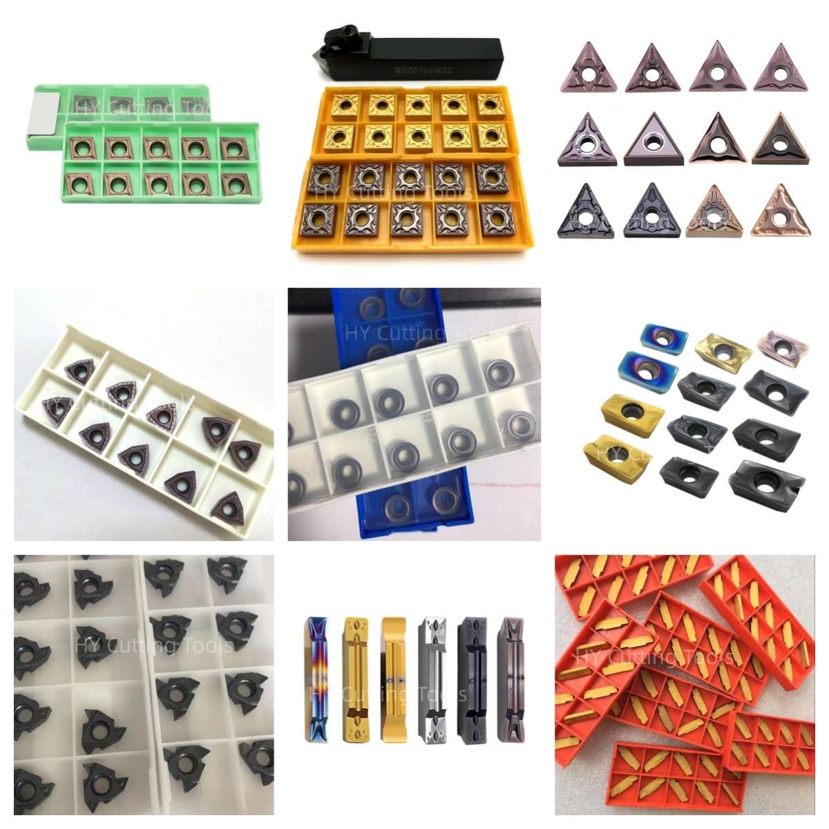

Share a line-by-line list of insert codes and quantities for a mixed-size quotation. Stock status, minimum quantity, sample requirements and production lead time are confirmed for each grade, coating and configuration.
Send your item list and quality requirements through our contact form for specification, availability and delivery confirmation.
◆Product FAQs
What is the difference between turning and milling inserts?
A turning insert is held in a lathe toolholder while the workpiece rotates. A milling insert rotates with a cutter body and repeatedly enters the cut. Their pocket, clamping, geometry and cutting data must be selected for the corresponding tool system.
Which turning insert families does this range cover?
The Overview names CNMG, DNMG, SNMG, TNMG, VNMG and WNMG as common turning families, plus APMT and other cutter-specific milling geometries. These are range examples, not a complete list of stocked codes. Send the full model for an exact size and grade check.
Can inserts with the same shape or ISO size be substituted?
Matching shape and nominal dimensions are only the first checks. Compare the complete code, thickness, corner radius, fixing hole, chipbreaker, grade, edge preparation and holder or cutter-pocket fit. Test the candidate under the actual cutting conditions before approving a production replacement.
How do I select a grade for steel, stainless steel or cast iron?
Provide the exact workpiece grade and hardness, operation, continuous or interrupted cut, coolant and current wear pattern. Then match a supplier-defined carbide grade and chipbreaker. ISO material groups are starting categories; a family name alone does not identify an approved grade.
Should I choose PVD, CVD or an uncoated insert?
The suitable surface treatment depends on the substrate, edge preparation, workpiece and cutting load. Confirm which coating is offered for the complete code and use its recommended operating range. A similar-looking coating does not establish equivalent performance.
Where can I find exact insert dimensions and cutting parameters?
This broad product page does not contain a verified size chart for every turning and milling family. Request the selected series drawing and grade-specific cutting data using the full insert designation and holder or cutter-body model. The APMT1135 / APMT1604 series provides a focused milling reference.
◆Ordering & OEM FAQs
Can I order different insert models together?
Send a line-by-line list with each complete insert code, grade and quantity. Mixed-model supply, minimum quantities and lead times are confirmed by item. The Overview lists 10 pieces per box as a reference; the actual pack quantity can differ by model.
What should I send for an insert replacement request?
Provide the original manufacturer and complete code, grade and chipbreaker, box-label photo, insert photos from both sides, holder or cutter-body model, workpiece, cutting conditions, observed wear and required quantity. This allows dimensional and application review before a sample trial.
Are private-label packaging and custom specifications available?
The Overview lists OEM and ODM services. Send the requested grade, geometry, marking, label artwork, packaging, quantity and target application for feasibility review. The approved drawing and quotation should identify the actual specification and lead time.
Can I request samples before a larger order?
Include the full codes, holder details, material and trial conditions with your inquiry. Confirm sample availability and quantity by model, then compare wear, finish, chip control and cost per accepted part under consistent machining conditions.
◆Guides & Technical References
Use the CNC Insert Selection Guide for turning shape, grade, nose-radius and chipbreaker checks. The Carbide Insert Types Guide explains the wider insert families.
For a model-specific drawing or quotation, send the full insert and holder codes along with your material, application and quantity.
Need Sizes, Pricing or Custom Options?
Send us the required tool type, sizes, quantities, workpiece material and any OEM or custom requirements. We will confirm suitable specifications, availability, lead time and quotation details.
Drawings, size lists and reference photos are welcome.