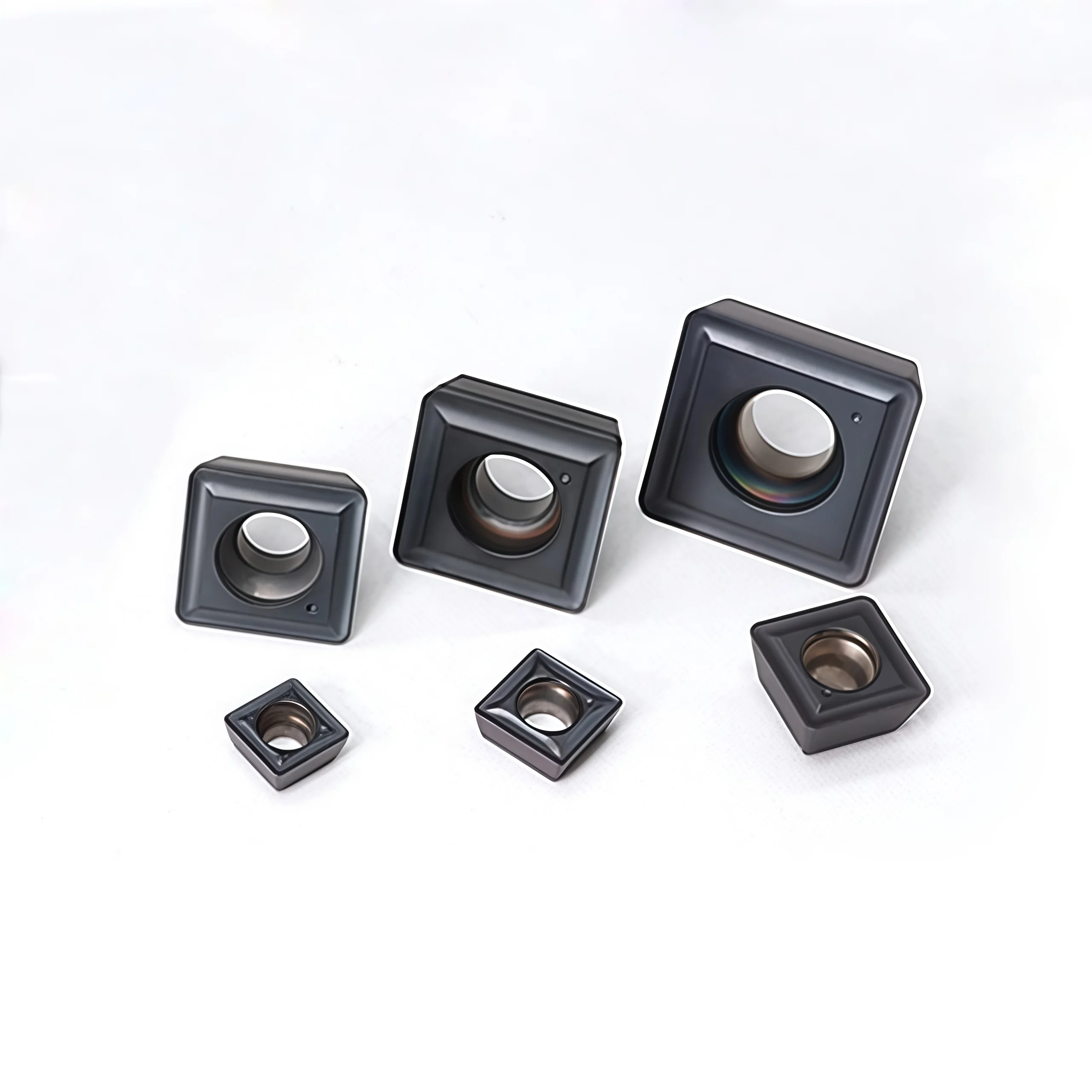
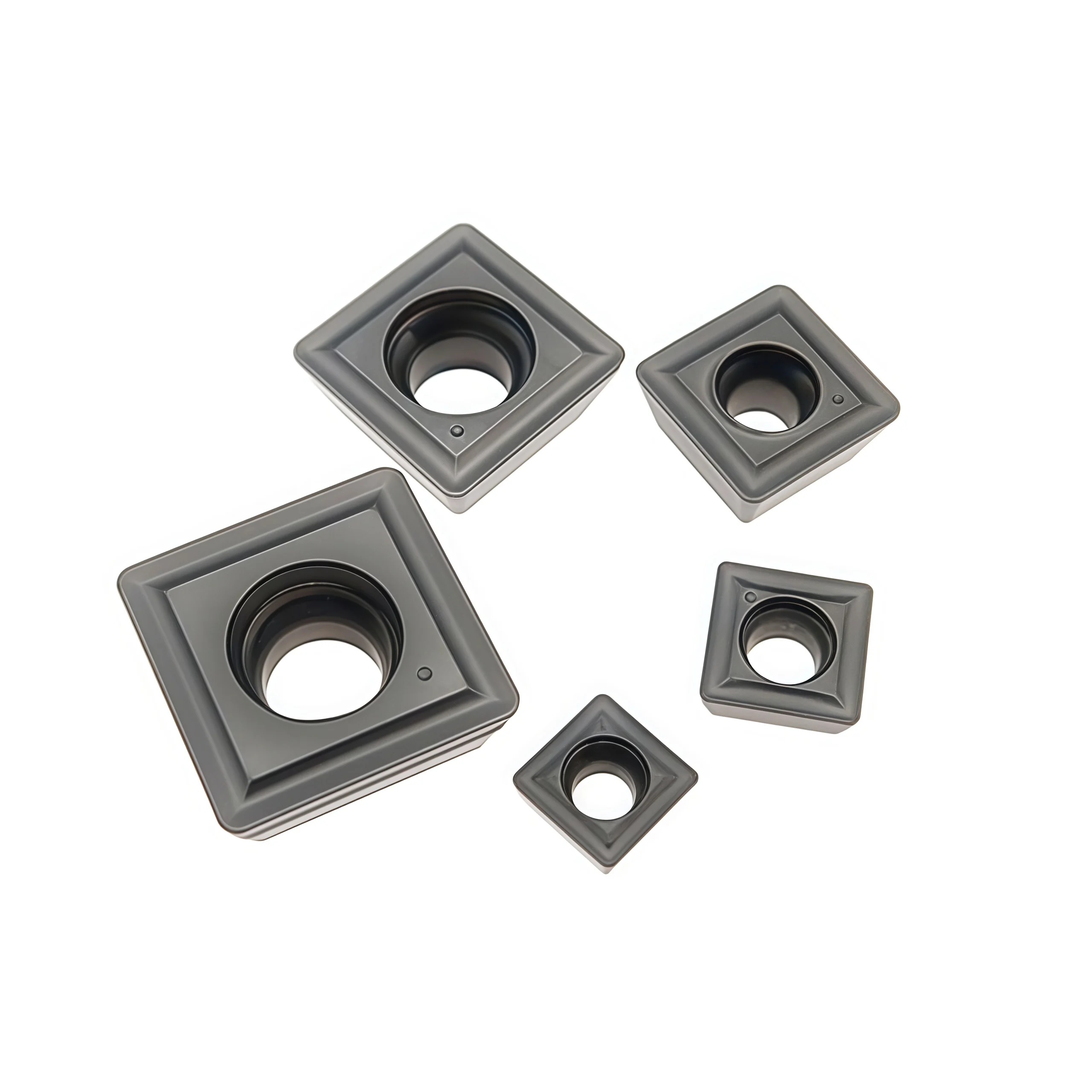
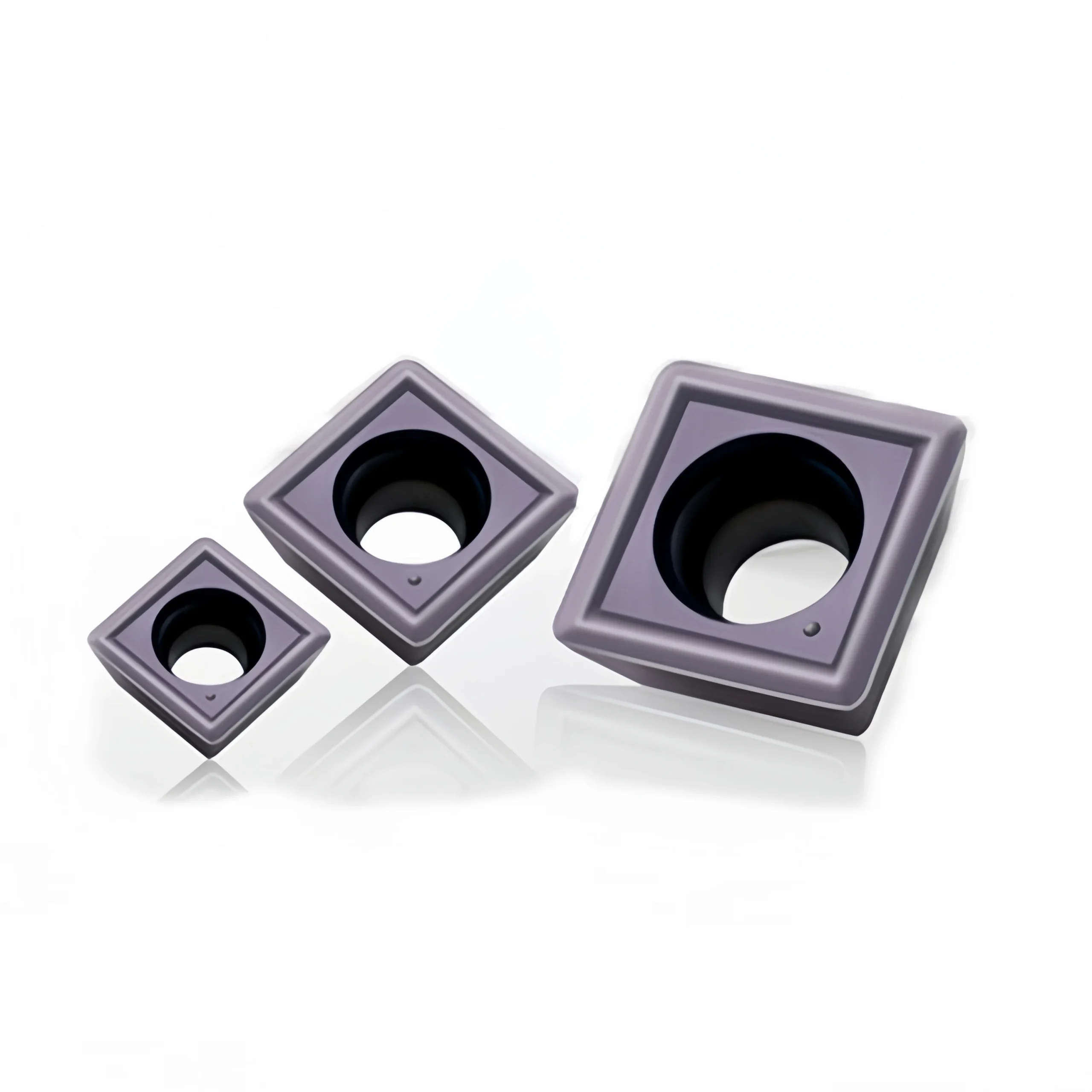
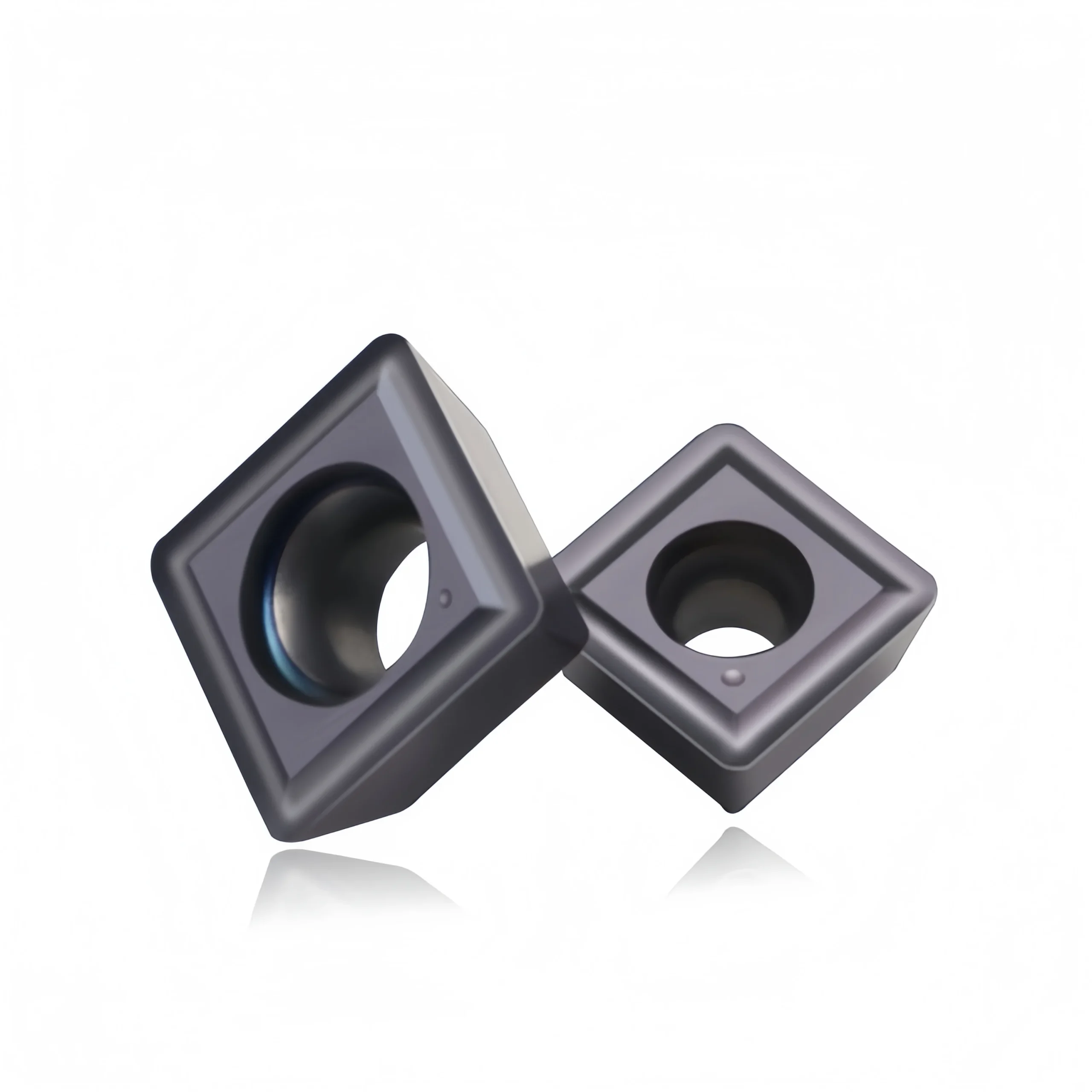
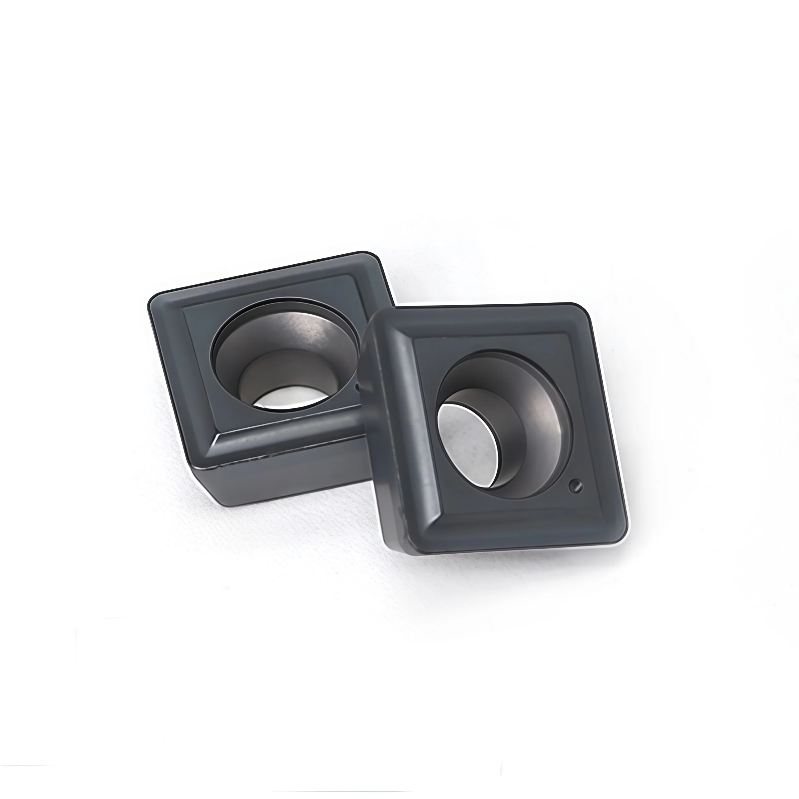

SPMT/SPMG Carbide Inserts for Indexable U-Drills
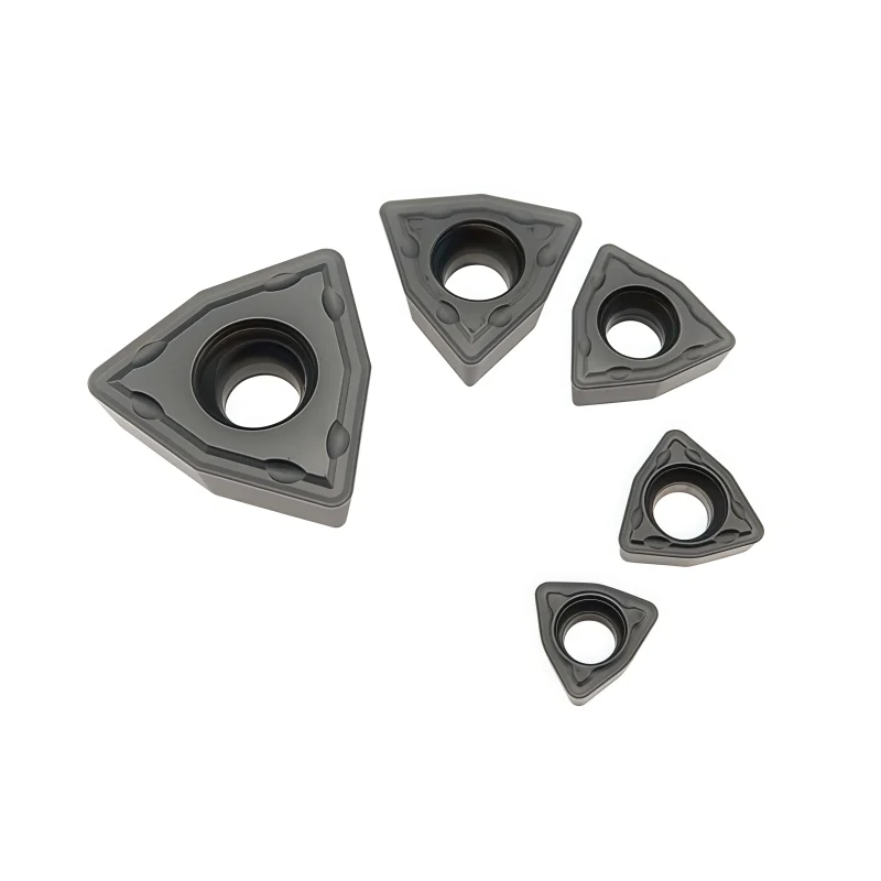
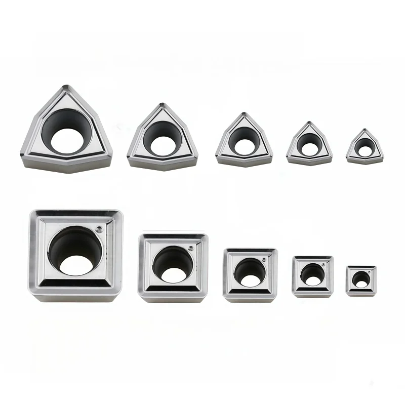
SPMT and SPMG square carbide inserts are designed for compatible indexable U-drill systems. Multiple sizes, grades and coatings can be selected according to drill position and workpiece material, allowing wholesalers to supply replacement inserts for general holemaking in steel, stainless steel and cast iron.
Consistent Quality
Consistent geometry across repeat orders.
Flexible Orders
Small batches and mixed sizes available.
OEM Support
Custom marking, labels and packaging.
Standard & Custom
Standard sizes and custom configurations.
Product Overview
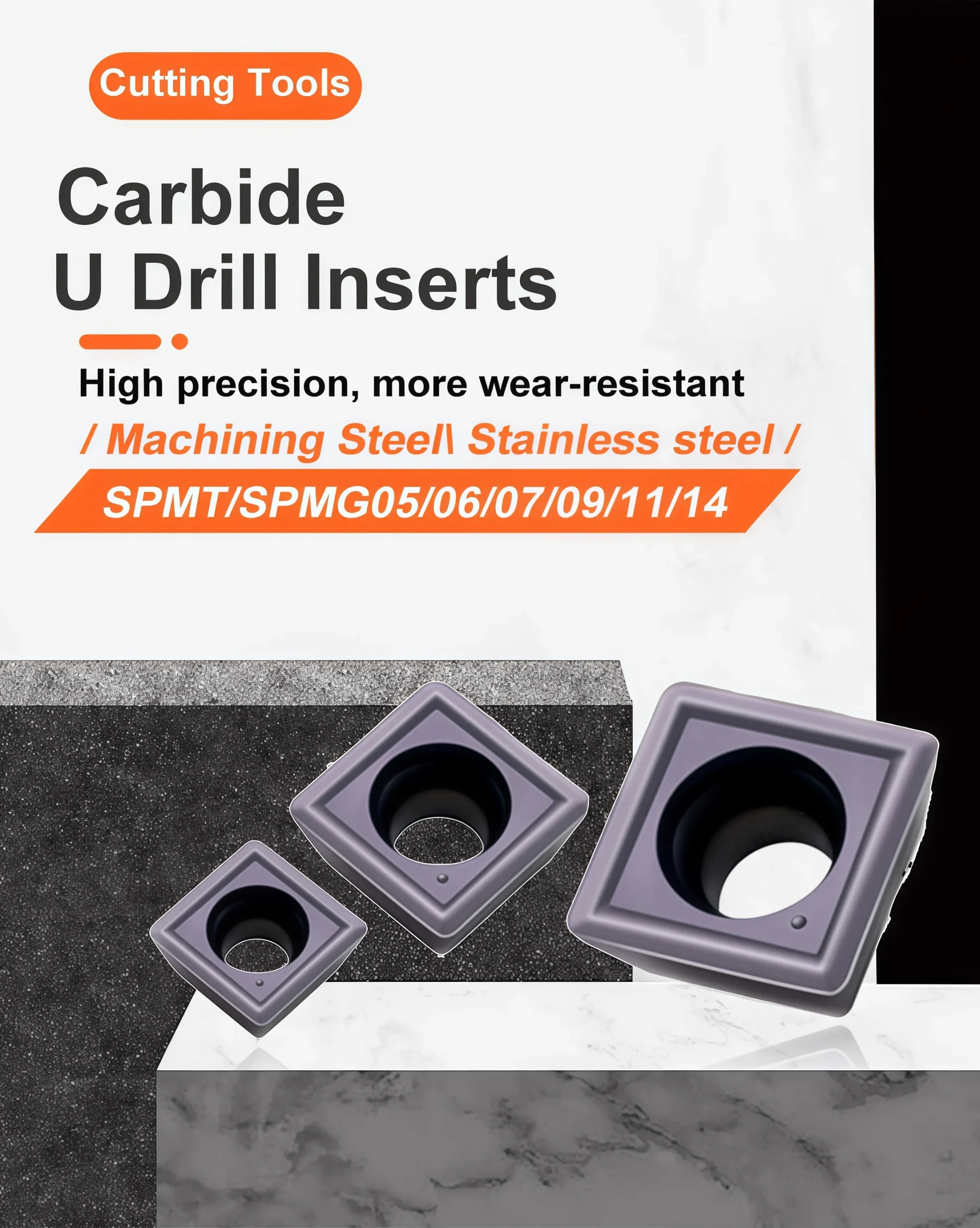
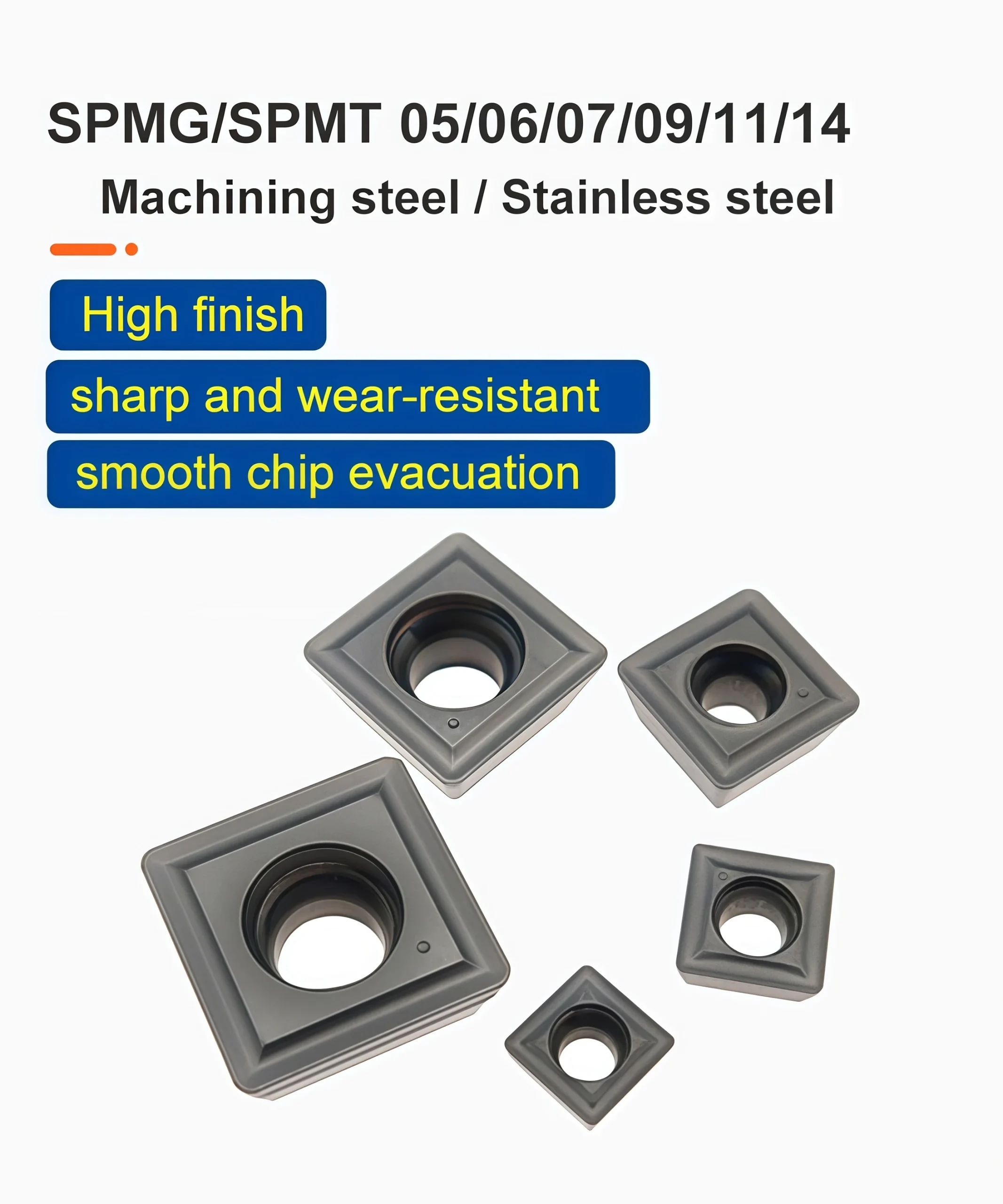
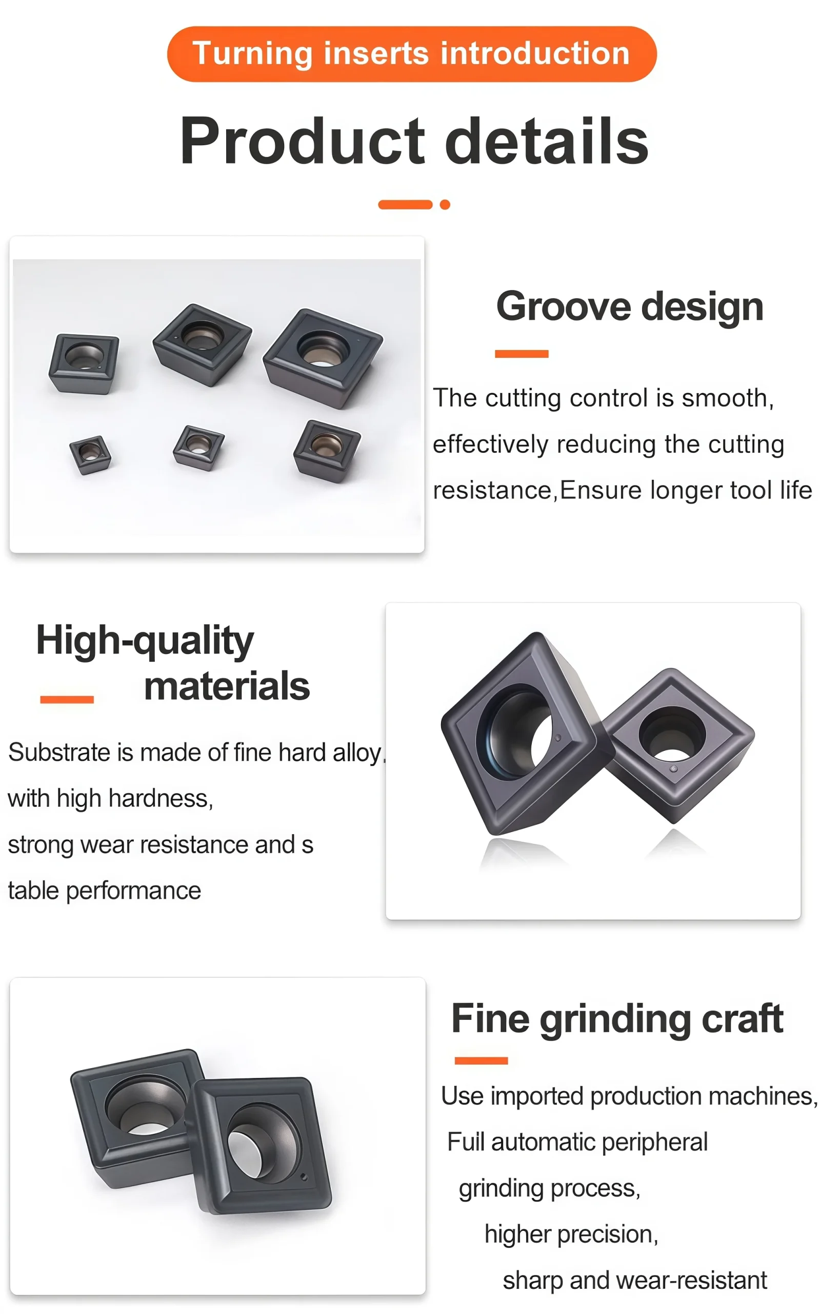
The SPMT / SPMG Tungsten Carbide U-Drill Inserts are engineered to deliver superior performance in CNC drilling and turning applications. Designed for use with indexable U-drill systems, these inserts provide excellent cutting stability, long tool life, and precise hole-making across a wide range of materials. With sharp edges and optimized chip-breaker geometry, they ensure low cutting resistance and efficient chip evacuation, making them ideal for high-speed and high-accuracy machining environments.
Key Features
-
High-performance cutting edges for smooth, stable drilling
-
Optimized geometry specifically designed for U-drill applications
-
Ultra-fine grain carbide substrate for increased durability
-
Efficient chip evacuation for cleaner and more consistent hole quality
-
Compatible with various indexable U-drill holders
-
Suitable for high-speed CNC machining
Advantages
-
Enhanced hole accuracy and superior surface finish
-
Lower cutting force reduces spindle load and tool wear
-
Improved machining efficiency and shorter cycle times
-
Longer service life with consistent performance in large-volume production
-
Cost-effective and easy to replace, reducing overall tooling costs
Applications
-
CNC U-drill operations
-
Precision hole-making in steel, stainless steel, cast iron, and non-ferrous materials
-
Automotive parts manufacturing
-
Aerospace component machining
-
General CNC turning and drilling tasks in industrial production
| Parameter | Description |
|---|---|
| Model | SPMG05 / 06 / 07 / 09 / 11 / 14 U Drill Insert |
| Material | Carbide |
| Workpiece | Aluminum / Copper / Steel / Hardened Steel / Stainless Steel / Cast Iron |
| Processing | Finishing, Semi-finishing, Roughing |
| Coating | CVD / PVD Coating |
| Color | Gray |
| MOQ Quantity | 10 Pieces |
| Package | 10 pcs / box |


SPMT/SPMG U-Drill Insert Specifications
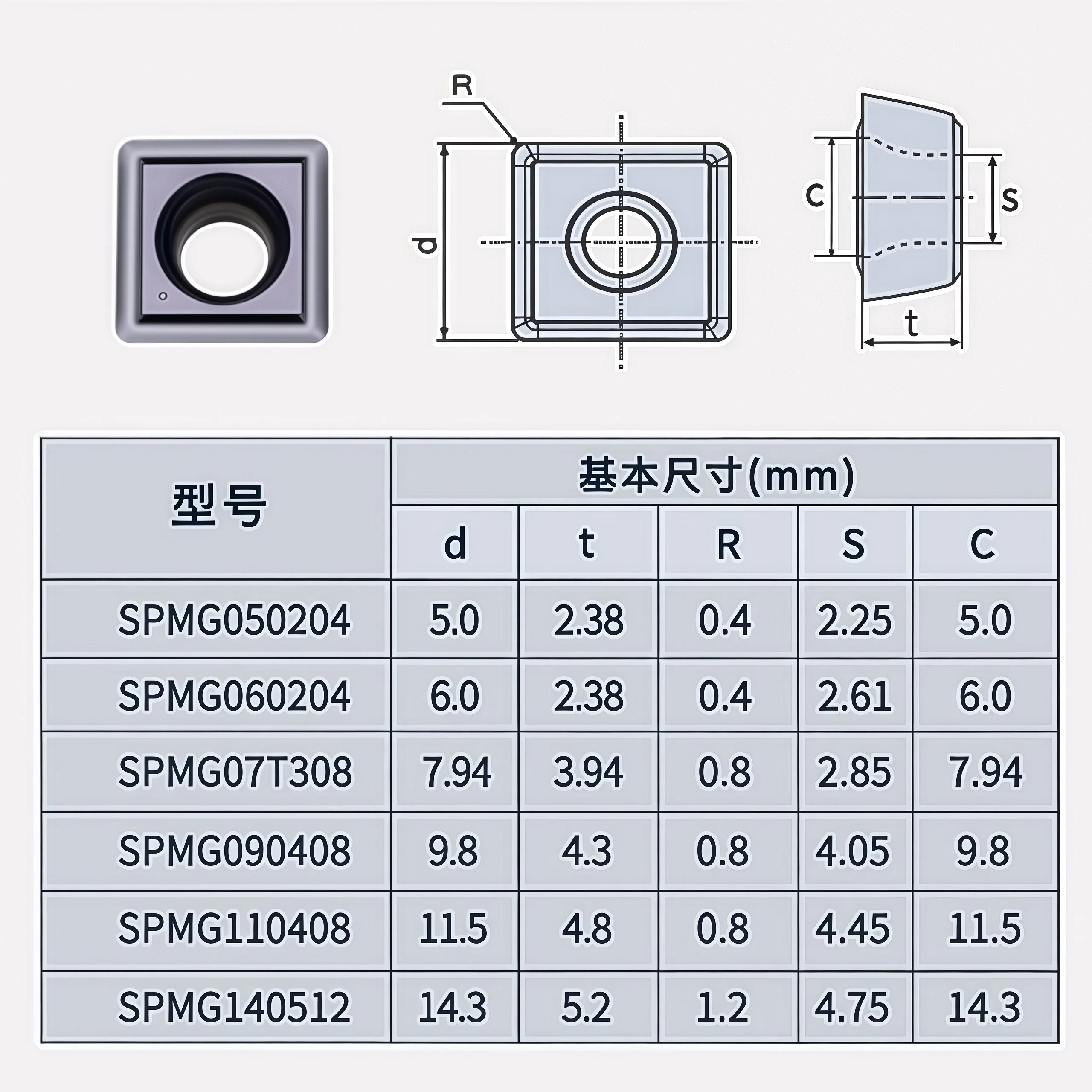
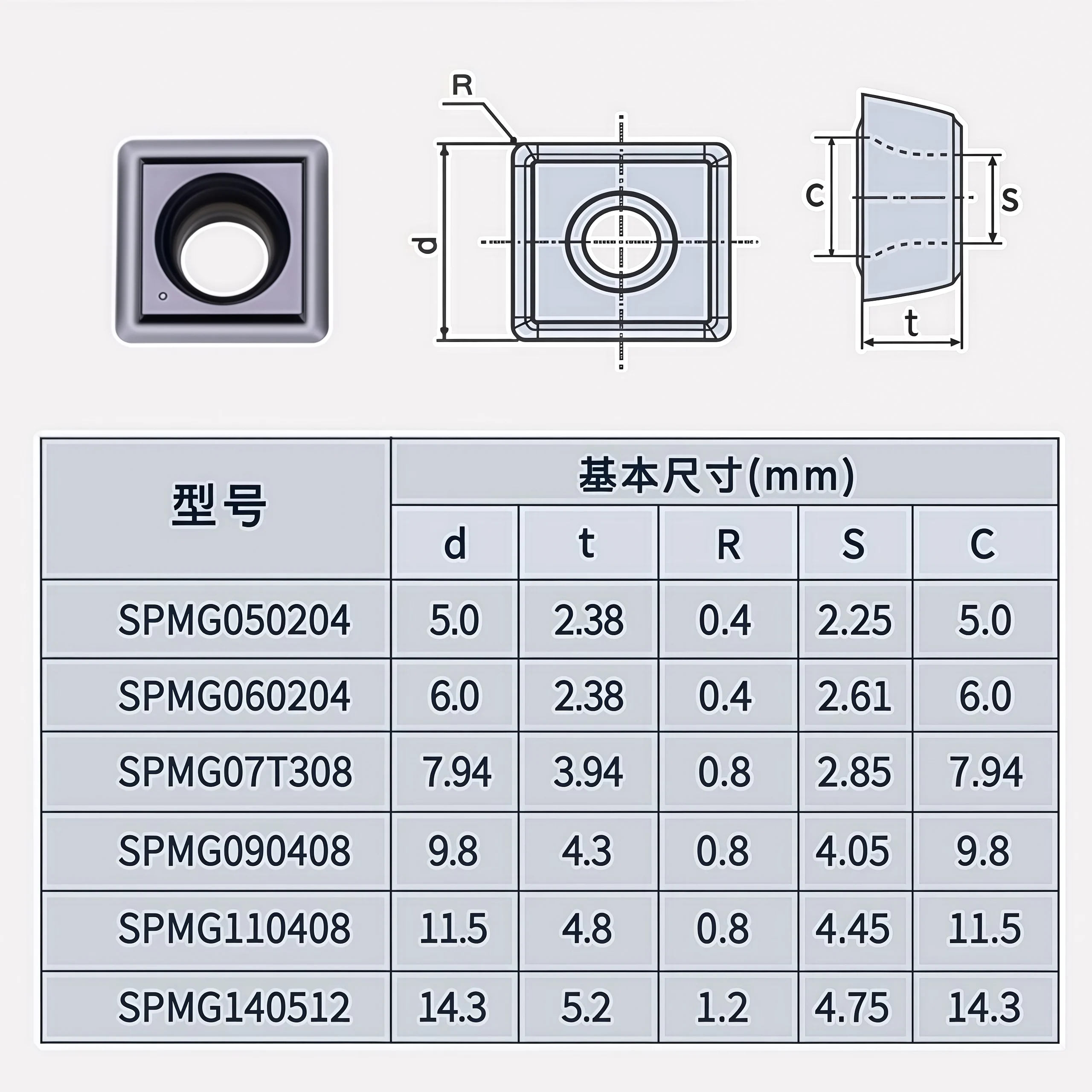
This range covers square carbide inserts for compatible indexable U-drills. The supplied drawing provides dimensions for six SPMG models, from SPMG050204 to SPMG140512. SPMT is part of the named product range, but no SPMT size chart or complete SPMT order codes are supplied here. Select the full insert code and drill-body pocket before ordering.
| Parameter | Specification / selection check |
|---|---|
| Insert families | SPMT / SPMG; match the exact family and complete designation to the specified drill pocket. |
| Dimensioned models | SPMG050204, 060204, 07T308, 090408, 110408 and 140512. |
| Tool material | Carbide; confirm the ordered substrate grade, coating and chipformer. |
| Application | Indexable drilling. Grade-dependent selection for steel, stainless steel, cast iron or non-ferrous materials; verify the exact workpiece and insert configuration. |
| Drill-body fit | Confirm pocket dimensions, seat, screw and center/peripheral position against the drill-body maker's insert list. |
| Supply reference | Legacy listing states MOQ 10 pieces and 10 pieces per box; confirm for each ordered code. |
SPMG Size Chart
Dimensions below reproduce the supplied SPMG drawing in millimeters. The labels d, t, R, S and C follow the illustration; R is the corner radius. Use the drawing to check the feature locations and confirm the insert seat against your drill-body specification.
| Model | d (mm) | t (mm) | R (mm) | S (mm) | C (mm) |
|---|---|---|---|---|---|
| SPMG050204 | 5.0 | 2.38 | 0.4 | 2.25 | 5.0 |
| SPMG060204 | 6.0 | 2.38 | 0.4 | 2.61 | 6.0 |
| SPMG07T308 | 7.94 | 3.94 | 0.8 | 2.85 | 7.94 |
| SPMG090408 | 9.8 | 4.3 | 0.8 | 4.05 | 9.8 |
| SPMG110408 | 11.5 | 4.8 | 0.8 | 4.45 | 11.5 |
| SPMG140512 | 14.3 | 5.2 | 1.2 | 4.75 | 14.3 |
Selection & Application Notes
Drill compatibility: Give the maker and full drill-body code, pocket position and current insert code. The same nominal insert size or square outline does not establish a compatible seat.
Material and geometry: Select grade, edge preparation, chipformer and coating for the workpiece and inner/outer position. The legacy page lists CVD and PVD as options, without assigning either coating to a specific size or grade.
Hole and cutting data: Finished hole diameter and speed/feed values depend on the complete drill body, insert combination, material, hole depth and coolant. Validate the assembly with a trial cut; this size chart is an insert drawing, not a drill-diameter chart.
Request an Exact Match
For SPMT dimensions, an SPMG replacement or grade-specific cutting data, send the full drill-body and insert designations, photos of the current insert and pocket, workpiece grade, hole diameter/depth and required quantity.
◆Carbide Insert Customization & OEM
Specify the insert around the machining operation, workpiece and holder. We can review standard replacements, application-specific geometry and private-label requirements using your insert designation, drawing or sample. Available grades, coatings, dimensions and order quantities are confirmed for each requested series.
Geometry & Chip Control
Review chipbreaker, rake, cutting-edge preparation, nose radius and corner design for the operation and workpiece. Confirm holder compatibility before approving a modified geometry.
Substrate & Coating
Select an available carbide grade and coating for the workpiece material, cutting conditions and desired balance of wear resistance and edge toughness.
Dimensions & OEM
Review insert size, thickness, locating and clamping features, tolerances, laser marking and private-label packaging against the approved specification.
◆Customization Options
Use the fields below when sending an inquiry. The exact options depend on the insert family and are confirmed in the quotation or approved drawing.
| Specification | Details to Confirm |
|---|---|
| Insert Type | Turning, milling, threading, grooving or drilling insert; send the designation or drawing. |
| Size & Fit | Shape, size, thickness, inscribed circle or edge length, hole or clamping form, and holder model. |
| Cutting Geometry | Chipbreaker, nose or corner radius, edge preparation, cutting direction and application-specific profile. |
| Grade & Coating | Workpiece group and grade, carbide substrate, coating system and wet or dry cutting conditions. |
| Tolerance & Inspection | Critical dimensions, profile requirements, inspection method and any required report. |
| OEM Presentation | Insert or box marking, label content, packaging format and quantity per pack. |
◆How to Request a Custom Insert

Send your insert requirements through our contact form or review our OEM and private-label service.
◆Carbide Insert Quality Control

Insert quality depends on the approved grade, geometry, coating and dimensional specification. We review the requirements at order confirmation and align the inspection scope with the insert series and any customer drawing. Share critical dimensions or documentation needs before production so they can be included in the agreed inspection plan.
01 · Incoming Material
Confirm the specified carbide grade or material documentation against the order requirements.
02 · In-Process Checks
Review dimensions and cutting-edge features during production against the approved specification.
03 · Final Inspection
Check the agreed dimensions, appearance, edge condition, coating identification and marking as applicable.
04 · Packing Review
Verify the item code, quantity, labels and protective packing against the approved order.
◆Inspection & Documentation
Inspection points and acceptance criteria should be agreed for the ordered series. For custom inserts, the approved drawing takes priority over a generic catalogue description.
| Check Area | What to Confirm |
|---|---|
| Dimensions & Fit | Insert size, thickness, corner radius, clamping features and any drawing tolerances. |
| Cutting Geometry | Chipbreaker, edge preparation, usable corners and profile where applicable. |
| Grade & Coating | Approved grade and coating designation; any requested verification method. |
| Appearance & Packing | Visible edge damage, marking, item code, count and packing format. |
| Requested Records | Inspection report, material or coating documentation, sample approval or batch identification when agreed. |
◆Order & Delivery
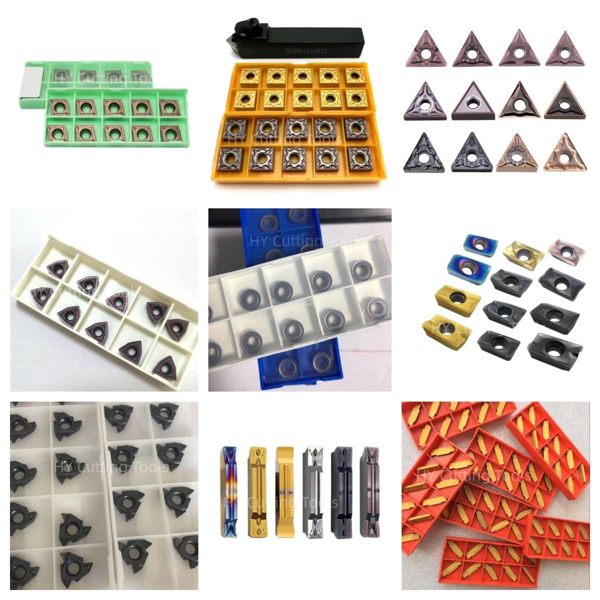

Share a line-by-line list of insert codes and quantities for a mixed-size quotation. Stock status, minimum quantity, sample requirements and production lead time are confirmed for each grade, coating and configuration.
Send your item list and quality requirements through our contact form for specification, availability and delivery confirmation.
Product FAQs
Which SPMT and SPMG sizes have published dimensions here?
The supplied chart gives d, t, R, S and C for SPMG050204, SPMG060204, SPMG07T308, SPMG090408, SPMG110408 and SPMG140512. It does not give SPMT codes or SPMT dimensions; request the drawing for the specific SPMT insert.
Can I replace an SPMT insert with an SPMG insert of the same nominal size?
Do not assume interchangeability. Compare the full designation, dimensional tolerance, locating and clamping surfaces, chipformer, screw and approved pocket list for the exact U-drill body.
Do the chart dimensions indicate the drilled-hole diameter?
No. The chart describes insert geometry in millimeters. The complete drill-body model defines its nominal drilling diameter; actual hole size also depends on setup and cutting conditions.
Do center and peripheral pockets use the same grade?
It depends on the drill system and material. Use the drill maker's specified insert codes and positions; the center and outer pockets may need different grades or geometries.
Which materials can these inserts drill?
Options may be selected for steel, stainless steel, cast iron and non-ferrous alloys, depending on the complete carbide grade, coating and chipformer. The legacy list also names hardened steel, but that application is not verified for the six charted models; confirm it separately before use.
What cutting speed and feed should I use?
Start with cutting data for the approved drill body, insert grade and workpiece. Account for drill diameter, depth, coolant and machine rigidity, then check chip evacuation, hole size and edge wear during a trial cut. The size chart contains no cutting parameters.
Ordering & OEM FAQs
What should I provide for a replacement quotation?
Send the drill-body maker and complete code, current insert designation and grade, photos of the insert and pocket, center/outer position, workpiece grade, hole diameter/depth and quantity.
Can SPMT and SPMG sizes be combined in one order?
List each full item code, grade, coating and quantity as a separate line. Mixed-size supply and availability are confirmed for each configuration.
What are the minimum order and box quantity?
The supplied legacy listing says 10 pieces minimum and 10 pieces per box. Confirm the terms for the selected SPMT or SPMG code in the quotation.
Are samples and private-label packaging available?
Share the exact insert configuration, drill-body code, trial conditions, order quantity and artwork requirements. Sample supply and OEM marking or packaging are reviewed by item.
Guides & Technical References
Read our CNC Insert Selection Guide for grade, geometry and application checks.
For an exact SPMT drawing, SPMG grade or quotation, send the complete drill-body and insert codes.
Need Sizes, Pricing or Custom Options?
Send us the required tool type, sizes, quantities, workpiece material and any OEM or custom requirements. We will confirm suitable specifications, availability, lead time and quotation details.
Drawings, size lists and reference photos are welcome.